The Power of Air: How Pneumatic Brake Actuation Systems Stop Heavy Vehicles
When a truck driver presses the brake pedal, they are not pushing on a hydraulic master cylinder like in a car. Instead, they are opening a valve that releases compressed air. Pneumatic Brake Actuation Systems use the energy stored in compressed air to apply the brakes, leveraging the immense force multiplication possible with pneumatics. These systems are the standard for commercial vehicles because they are fail-safe, reliable, and compatible with trailers. Working alongside Vehicle Safety and Braking Solutions, pneumatic actuation provides the stopping power needed for heavy-duty applications.
Why Air? The Pneumatic Advantage
Passenger vehicles use hydraulic brakes (fluid under pressure). Commercial vehicles use pneumatic brakes (air under pressure). The reasons are fundamental:
| Aspect | Hydraulic (Car) | Pneumatic (Truck) |
|---|---|---|
| Power source | Brake fluid (incompressible) | Compressed air (compressible) |
| Force transmission | Instant (fluid does not compress) | Slight delay (air compresses) |
| Failure mode | Loss of fluid = complete failure | Loss of air = gradual failure (spring brakes engage) |
| Leak detection | Fluid leaks may go unnoticed (slow leak) | Air leaks are audible; pressure loss is monitored |
| Trailers | Complex (requires hydraulic coupler) | Simple (air line coupling) |
| Parking brake | Separate mechanical system | Spring brakes (air releases, spring applies) |
The Compressibility Factor: A Feature, Not a Bug
Air compressibility is both an advantage and a challenge.
Advantage (Cushioning):
Air acts as a spring, reducing shock loading on brake components. When the brakes are applied suddenly, the air compresses slightly, smoothing the force application. This reduces wear on chambers, slack adjusters, and calipers.
Challenge (Delay):
Because air must flow through lines and compress before force reaches the wheels, there is a slight delay between pedal application and brake actuation. Modern systems minimize this through relay valves placed near the wheels.
The Actuation Sequence: Step by Step
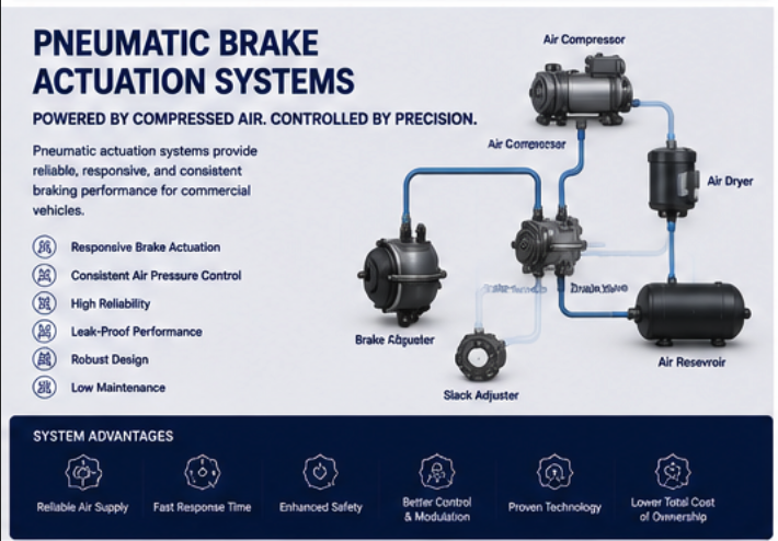
Step 1: Air Generation and Storage
-
The engine-driven air compressor draws in atmospheric air and compresses it to 120-150 psi.
-
The air dryer removes moisture and oil vapor.
-
Compressed air flows to reservoirs (air tanks) for storage.
-
The governor controls compressor operation, unloading it when pressure reaches cut-out.
Step 2: Driver Input
-
The driver presses the brake pedal (treadle valve).
-
The treadle valve opens, releasing a small amount of "control" air pressure.
-
The control pressure is proportional to pedal position (e.g., 10% pedal = 15 psi, 100% pedal = 120 psi).
Step 3: Control Signal Transmission
-
Control air travels through small-diameter lines to relay valves near the axles.
-
Because the volume of control air is small, it travels quickly (minimal delay).
Step 4: Relay Valve Activation
-
The control air pressure acts on the relay valve's piston.
-
The relay valve opens, allowing high-volume air from the reservoir to flow to the brake chambers.
-
The relay valve can deliver air much faster than the foot valve alone.
Step 5: Brake Chamber Actuation
-
Air enters the brake chamber, pushing against a flexible diaphragm.
-
The diaphragm pushes a pressure plate, which extends the pushrod.
-
Pushrod force is applied to the slack adjuster.
Step 6: Force Multiplication
-
The slack adjuster multiplies the pushrod force.
-
The caliper clamps the brake pads against the rotor.
-
Friction converts kinetic energy to heat, slowing the vehicle.
Step 7: Release
-
The driver releases the brake pedal.
-
Control air is exhausted through the foot valve.
-
The relay valve closes, and the quick-release valve opens, exhausting air from the chambers.
-
The return spring in the brake chamber retracts the pushrod.
-
Brake pads release from the rotor.
Key Components of Pneumatic Actuation
Pneumatic Brake Actuation Systems rely on several critical components:
1. Brake Chamber (Air Cylinder):
-
Function: Converts air pressure into pushrod force.
-
Type: Service chamber (brake apply) or spring brake chamber (parking/emergency).
-
Pushrod stroke: 1.5-2.5 inches at full application.
2. Treadle Valve (Foot Valve):
-
Function: Driver interface; output pressure proportional to pedal position.
-
Dual-circuit: Two independent output ports (safety redundancy).
3. Relay Valve:
-
Function: Delivers high-volume air to chambers near wheels. Reduces delay.
-
Control: Small pressure from foot valve controls large flow from reservoir.
4. Quick Release Valve:
-
Function: Rapidly exhausts air from brake chambers when released.
5. Automatic Slack Adjuster:
-
Function: Maintains proper pad-to-rotor clearance automatically.
Spring Brakes: The Fail-Safe Feature
Spring brakes (parking/emergency brakes) are an integral part of pneumatic actuation.
Construction:
-
Service section: Normal pneumatic brake (air applies).
-
Spring section: Large coil spring (air releases).
Operation:
-
Normal driving: Air pressure holds the spring in the compressed (released) position.
-
Parking brake applied: Driver exhausts air from spring section; spring expands, applying brake.
-
Emergency (air loss): If system pressure drops below spring brake threshold (typically 40-60 psi), spring brakes apply automatically.
Caging the Spring (Emergency Release):
If the vehicle loses air pressure and spring brakes apply (e.g., a tow situation), a mechanic can "cage" the spring using a caging bolt, manually releasing the brake.
Air Pressure and Brake Force
The force applied to the brake pads is directly proportional to air pressure:
Example (Type 30 Chamber, 100 psi):
-
Chamber effective area: 30 in² (nominal)
-
Pushrod force: 100 psi × 30 in² = 3,000 lbs
-
Slack adjuster advantage: 10:1 (typical)
-
Caliper clamping force: 10,000+ lbs
A single brake chamber can generate over 5 tons of clamping force at 100 psi.
Air System Pressure Management
The pneumatic system maintains pressure between cut-in and cut-out:
| Parameter | Typical Value | Consequence |
|---|---|---|
| Governor cut-out | 130-135 psi | Compressor unloads |
| Governor cut-in | 105-110 psi | Compressor loads |
| Low pressure warning | 60-65 psi | Warning light and buzzer |
| Spring brake apply | 40-60 psi | Springs engage automatically |
Low Pressure Warning:
When pressure drops below 65 psi, a warning light and buzzer alert the driver. The vehicle may still stop normally, but the margin is reduced.
Spring Brake Apply:
If pressure continues to drop below 40-60 psi, spring brakes automatically apply. The vehicle will stop gradually (not abruptly) but cannot move until pressure is restored.
Pneumatic vs. Electropneumatic (EBS)
Traditional pneumatic actuation is purely mechanical. Modern Electronic Braking Systems (EBS) add electronic control:
| Feature | Traditional Pneumatic | Electropneumatic (EBS) |
|---|---|---|
| Pedal sensor | Air pressure | Electronic position sensor |
| Control signal | Air pressure | Electric signal |
| Response time | 0.2-0.5 seconds | 0.1-0.2 seconds |
| Integration with ABS/ESC | Limited | Full integration |
| Trailer control | Less precise | Precise, coordinated |
EBS is becoming standard on new trucks in Europe and North America.
Maintenance of Pneumatic Systems
Vehicle Safety and Braking Solutions require regular pneumatic system maintenance:
| Task | Interval | Procedure |
|---|---|---|
| Drain air tanks | Daily | Open drain valves; release moisture |
| Check for air leaks | Weekly | Listen for hissing; use soapy water |
| Check pushrod stroke | Monthly | Measure travel; adjust if out of spec |
| Replace air dryer filter | Annually | Prevents moisture contamination |
| Lubricate slack adjusters | Every 50,000 miles | Grease fittings |
| Test spring brakes | Monthly | Apply parking brake on slight grade |
Common Pneumatic Problems and Solutions
| Problem | Cause | Solution |
|---|---|---|
| Slow brake application | Restricted air line, faulty relay valve | Inspect lines; replace relay valve |
| Brakes do not release | Stuck relay valve, frozen quick-release valve | Clean or replace valve |
| Low air pressure warning | Compressor failure, air leak, governor fault | Repair leak; replace faulty component |
| Spring brakes will not release | No air pressure, caged spring, failed dash valve | Build air pressure; release cage; replace dash valve |
| Brake drag (pads contact rotor) | Sealed slack adjuster not releasing, stuck caliper | Replace adjuster; rebuild caliper |
The Future of Pneumatic Actuation
-
EBS becoming standard: Electronic control reduces response time and improves trailer synchronization.
-
Integrated diagnostics: Sensors monitor stroke, pressure, and pad wear; transmit data to fleet management.
-
Electronically controlled parking brakes: Dash switch replaces pull valve; automatic application on driver exit.
-
Energy recovery: Trucks with pneumatic hybrid systems capture braking energy as compressed air.
Conclusion
The invisible force that stops a 40-ton truck is compressed air. Pneumatic Brake Actuation Systems transmit the driver's intent from pedal to pads with reliability and fail-safe redundancy. Spring brakes ensure that even with complete air loss, the vehicle will stop. As part of comprehensive Vehicle Safety and Braking Solutions, pneumatics provide the muscle that makes heavy vehicle braking possible.